Loading...
Note: these numbers are estimates, based on datasheets and measurements. They don't include everything and may be wrong.
The accelerometer that we are using, LIS3DH, starts in a low power mode. That’s not the case for all such sensors, many start up in an already enabled state that uses more power. Starting up to a low power mode means that we can ignore the accelerometer when we don’t use it and it won’t use more power than necessary, but it does mean we need to configure it before we can use it.
The beginning of the code on the right is the same as before, but now we do some magic:
	err = i2c.Tx(0x18, []byte{0x20, 0b0100_0111}, nil)
	if err != nil {
		println("got error while configuring the LIS3DH:", err.Error())
		return
	}
That’s a lot of magic numbers! Let’s go through them:
Internally, most I2C devices are organized as a number of registers. You can think of it as a slice of bytes, one that’s typically just 128 or so bytes long. This slice contains both configuration data (which can typically be read and written), and sensor output data (which is typically read-only). In one transaction, you can either read or write data to the I2C device:
r byte slice. This is what we did in the previous step of this tour, to read the WHO_AM_I register.To know what register 0x20 is, and what the value 0b0100_0111 means, we need to take another look at the datasheet:
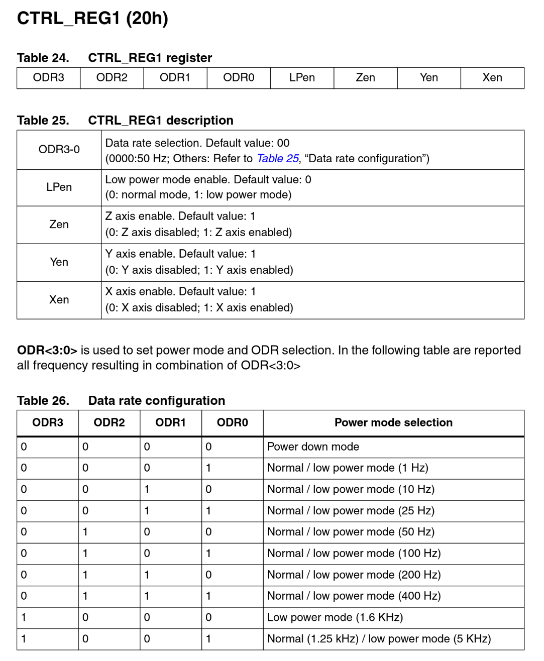
This section describes register CTRL_REG1 at address 20h. “20h” means “hexadecimal 20”, which is the same as 0x20 in Go.
The register itself contains 8 bits: 4 bits for “ODR”, one for “LPen”, and 3 bits for the three axes (Z, Y, X).
Decoding our value 0b0100_0111 (starting from the lowest bits on the right), we see the following:
Now if you look at the “Properties” tab on the right, you can see that the LIS3DH is indeed configured as “Normal mode 50Hz, enabled axes X, Y, Z”, exactly what we wanted! If you go back one step (where we read the WHO_AM_I register) you can see it is set to “Power down mode” instead since that is the power-on default. Also, if you go to the “Power” tab, you can see that the LIS3DH now uses 11µA instead of 0.5µA as it did in power down mode.
Try changing the value 0b0100_0111 to something else, and see what happens in the simulator!
Note: these numbers are estimates, based on datasheets and measurements. They don't include everything and may be wrong.