I2C
For API documentation, see the machine API.
I2C is a widely used protocol for communication between chips because it requires only two digital pins on a microcontroller to communicate with multiple external devices on a single bus. It is not very fast however so it is primarily used for small sensors. An alternative name that is sometimes used is two-wire interface (or TWI), as it requires only two signal wires.
As said, I2C uses two wires for communication:
- SCL (or Serial Clock) provides a clock signal. It is always controlled by the bus controller (usually the microcontroller).
- SDA (or Serial Data) goes both ways: data goes from the controller to the peripheral or from the peripheral to the controller. The protocol ensures that this goes smoothly.
One important property of I2C is that multiple devices can be used on a single bus. That is, the two wires of I2C (SCL and SDA) can be connected to multiple peripheral devices. That means you can control many different peripheral devices using just two wires on the microcontroller, which is useful as pins tend to be scarce.
The downside of all these features is that the protocol is not very fast. Most devices support 100kbps or 400kbps, but higher speeds aren’t usually used. If you need higher speeds, SPI is another protocol that needs more wires but can easily reach 4MHz or higher speeds. Therefore, SPI is often used for displays while I2C is often used for sensors.
If you want to learn more about I2C, you can read this guide on Sparkfun for more in-depth information.
Message format
To allow multiple I2C devices on a single bus, each device has an address. You should be able to find the address in the documentation of the peripheral. Many peripherals also let you pick between two (or more) addresses by setting certain pins to high or low, but generally there is one default address.
Apart from the peripheral address, the vast majority of I2C devices also use numbered registers. A typical read operation to read these registers is as follows:
- The controller starts a transaction by sending out the peripheral address.
- The controller writes a single byte, which is the register number to read.
- The controller reads one or more bytes from the peripheral. The first byte returned is for the register number that was set in step 2. Subsequent bytes are for subsequent registers, as the register number increases by one on each read.
- The controller stops the transaction when it has read enough bytes.
You could think of this auto-increment behavior as reading a file. Step 1 opens a file (f, err := os.Open()), step 2 seeks to a location in a file (f.Seek()), step 3 reads some data (f.Read()), and step 4 closes the file (f.Close()). This auto-increment behavior is often useful and peripheral devices tend to put related registers close together for this reason, so they can be quickly read in a single transaction.
Writing is very similar. The main difference is that the controller writes data to the peripheral instead of starting to read bytes after the initial register number is written to the peripheral.
Target mode
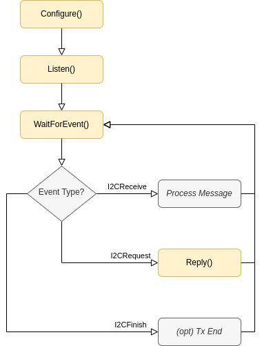
Typically, I2C peripherals are used in controller mode to communicate with sensors and other devices. In I2C target mode, the peripheral instead takes the role of the target (i.e. the role of a sensor/similar device). In this case, the application logic is responsible for processing and responding to messages initiated by an I2C controller, according to this flow diagram:
Interacting with a device
For this example, we’ll use the MPU6050 which is a very common (but old) sensor that measures acceleration and rotation. We won’t be doing much interesting with it, but it serves as a great introduction into how to work with I2C peripherals with TinyGo.
Here is the full code that we’ll use:
package main

import "machine"

func main() {
    i2c := machine.I2C0
    err := i2c.Configure(machine.I2CConfig{
        SCL: machine.P0_30,
        SDA: machine.P0_31,
    })
    if err != nil {
        println("could not configure I2C:", err)
        return
    }

    w := []byte{0x75}
    r := make([]byte, 1)
    err = i2c.Tx(0x68, w, r)
    if err != nil {
        println("could not interact with I2C device:", err)
        return
    }
    println("WHO_AM_I:", r[0]) // prints "WHO_AM_I: 104"
}
Let’s go through it line by line. The first step is configuring the I2C hardware of the microcontroller:
i2c.Configure(machine.I2CConfig{
    SCL: machine.P0_30, // change this
    SDA: machine.P0_31, // and this
})
This configures the microcontroller I2C hardware to use the given pins. It doesn’t yet interact with the external peripherals.
Note that you can’t just pick any pins. While some microcontrollers let you pick arbitrary pins, most are limited to just a few per I2C peripheral or do not let you pick pins at all.
If the board you’re using has designated I2C pins (often but not always printed on the silkscreen) you can also use a shorthand to use the default pins for that board:
i2c.Configure(machine.I2CConfig{})
Once I2C has been configured, we can start to communicate with the MPU6050.
w := []byte{0x75}
This creates a byte slice (of length 1) with the data that we’re going to send. The number 0x75 is the register number we’re going to read.
r := make([]byte, 1)
This allocates a buffer r for the receiving buffer. It is a byte slice of 1, so we’re going to receive just a single byte.
i2c.Tx(0x68, w, r)
This does the actual I2C transaction. It communicates with the peripheral at address 0x68, writes the data in buffer w, and then reads a single byte which will be stored in buffer r.
println("WHO_AM_I:", r[0])
The last line simply prints the received byte. The 0x75 register is the so-called “who am I” register, which can be useful to confirm that the I2C connection is working. In this case it is 0x68, which is received from the MPU6050 so our connection actually works! We read some data from the MPU6050!
To actually use this sensor you’d need to configure it first to start the sensor, but that’s outside the scope of this guide. Instead, if you want to actually use an MPU6050, there is a driver already. You can see an example here how to use it.
Behind the scenes
It may be helpful to know what is going on behind the scenes. However, if you just want to use I2C you can skip this section.
- The microcontroller sends a start signal on the bus and clocks out the address of the MPU6050 (0x68) plus a bit to indicate it is going to write.
- It then writes the 0x75 byte on the bus.
- The microcontroller then needs to switch over to reading. It does this by sending a repeated start on the bus and clocks out the MPU6050 address again but now indicating that it wishes to read.
- It reads a byte.
- It signals a stop condition on the bus, to end the transaction.
Here are the raw signals:
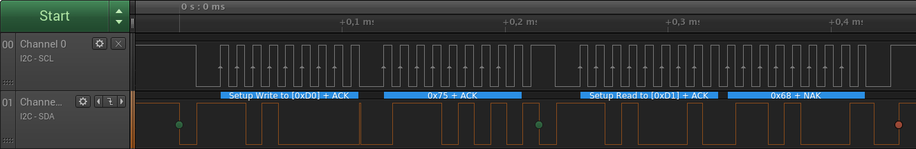
You can see the clock (SCL) is going up and down quickly and the data line somewhat more randomly as it sends data back and forth. Moreover, you can see that four bytes are transmitted across the wire: 0xD0, 0x75, 0xD1, and 0x68. 0xD0 and 0xD1 are the address, shifted left by one and with the read bit first set and then cleared. From this screenshot it is not visible who send the data, but in this case the last byte was sent by the MPU6050 and the previous three were sent by the microcontroller.